
For pin out details of the 20-pin connector and straightforward
interface circuits click
 .
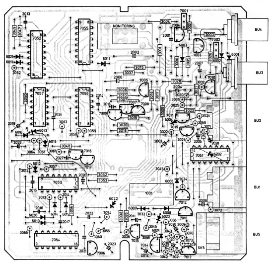
This page deals in detail with the 22AV5530 adaptor.
.
This page deals in detail with the 22AV5530 adaptor.
Power supply
The adapter is powered with 12 Vd.c. from the VCR. This voltage enters at point 3 of the 20-pole connector. The circuit around transistors 7001 and 7004 provides current limitation at 400 mA.Operation
There are 3 modes of operation.
- Playback
- Corresponds to high PB signal from VCR. This signal is low during playback.
- Recording
- Corresponds with REC signal from the VCR. This signal is low during recording. Or signalled from camera via a separate control line on BU1.
- Monitoring
- This mode enables a video and audio signal to be looped through via connector BU2.
Playback Mode
During playback operation a low signal PB is applied to pin 19 of the 20-pole connector. Through diode 6022 transistors 7003 and 7002 are then turned on and the switching signal +PB and PB1 is supplied to the collector of transistor 7002. This switching signal sets Relay 1001 and the electronic switches in IC7051 (4066) controlled by pins 5, 6 and 12 to Playback mode. Pin 13 of IC7051 is held low by diode 6007.The video output signal from the VCR appears on Pin 18 of the 20-pin connector and is applied, with appropriate biasing, to the base of transistor 7010. From this transistor this signal is transferred to BU4 and through transistor 7011 to BU2. It is also sent via relay contact to BU l, pin 2.
Pin 2 of the 20-pole connector provides the audio VCR audio output signal. It is connected to pins 4, 9 and 10 of IC7051. Output from Pin 8 of this IC is fed to audio socket BU5. Output from Pin 11 it is fed to connector BU2 and Output from Pin 3 to BU1.
Record mode (with REC signal from the VCR)
Full circuit (500k) |
During recording the VCR supplies a low signal to Pin 12 of the 20-pole connector. In addition when channel 00 is selected a high signal is generated at input EXO (Pin 16 of the 20-pole connector). The video and audio processing circuitry is then in the recording mode (or rest position). The relay contacts route the video input signal from connector BU1 to transistor 7005. In addition the video input signal on BU3 is also applied to the emitter of transistor 7005. This parallels up the two inputs from BU1 & 3. From the collector of this transistor the signal is applied to the video input of the VCR (Pin 17 of the 20-pole connector) thorough transistor 7008 which acts with transistor 7005 to provide the reuired signal gain.
The audio signal on BU1 gies to Pin 2 of IC7051. As Pin 13 is pulled high via R3045, the electronic switch is closed and the signal from Pin 1 is applied to the VCR via diode 6023 and C2011 and pin 1 of the 20-pole connector. If a microphone is used for recording switch SK5 is closed and transistors 7016 and 7015 are then turned on and the amplifier comprising transistors 7013 and 7014 receives the power supply voltage. Through diode 6024 and C2011 the amplified audio signal is applied to the VCR input. Because the emitter of transistor 7016 is connected to earth via SK5, the voltage on Pin 13 of 1C7051 becomes low and the audio signal from BU1 is disconnected.
Recording mode with camera
Full PCB (100k) |
Both during during recording and playback the junction of R3065 and C2025 is held low by diodes 6019 and 6020 under control of the VCR. In "Stop" the junction is also held low via diode 6018 and resistor R3064. By pressing the trigger switch on the camera a direct voltage of approx. 10 V is produced on Pin 1 of BUl. As a result of this Pin 6 of IC7057 becomes high, Pin 4 becomes low and Pin 3 becomes high. Through C2014 and R3048 Pin 8 of IC7056 goes high. Pin 9 is high because the VCR is set to channel 00. As a result of this Pin 10 becomes high and flip-flop 7053b is set. The Q-output of IC7053 becomes low. The reset input, Pin 12 of IC7052 becomes low, so that the astable multi-vibrator, constituted by C2017, R3047, R3049 and the NAND-gate and inverter in the IC, is started. The frequency of this multi-vibrator is 6.25 kHz. The binary counter 7052 divides this by 26 and 25.
IC7056b converts this signal into a clock pulse. This pulse is applied to Pin 10 of IC7055. The Q-output of flip-flop 7053a is set low by the reset signal from Q of 7053b on the clear input upon the first clock pulse. As a result of this the levels on gates 1 to 6 are read in in-parallel. By means of the clock pulse on Pin 10 this signal is read out serially via output Pin 12. This serial code, together with the clock pulse and the inverted 1/(26) pulse, is inverted via transistor 7017 and applied to the microprocessor in the VCR. As soon as outputs 1/(26), 1/(25) and 1/(29) are simultaneously high, flip-flop 7053b is reset and the 6.25 kHz oscillator is stopped.
When the trigger button on the camera is pressed again the 10V on Pin 1 of BU1 disappears and the output of IC7057a becomes high. Through C2017 and diode 6015 this high signal sets flip-flop 7053b, so that the above cycle is repeated. However, now a "key-release" code is transmitted.
The high signal from the output of IC7057b each time also sets monostable 7054a. Approx. 120 msecs after this monostable is reset again. Q becomes high and this high signal is again applied to flip-flop 7053b via C2016 and diode 6014 and also to monostable 7054b. Now the "stop" code is transmitted. After 120 msecs. the monostable 7054b is reset via C2015 and diode 6012 this signal starts the cycle again. However, now the "key-release signal" is transmitted. Transistor 7018 ensures that if no command is issued the output to the microprocessor in the VCR is high. If recording is not possible, for example as a result of end-of-tape or the absence of a tape, the input of 1C7057d will remain high. (Via diode 6019 no low level is applied.) As a result of this the 6.25 kHz signal is applied to the camera on the 10V switching voltage via C2026-2024. In the camera this signal causes a red LED to light up. This is an indication that no recording command is accepted.

BAW62 4822 130 30613
BZX79/C6V8 4822 130 34278
8ZX79/C13 4822 130 34195
BC548B 4822 130 40937
BC558B 4822 130 44197

CD4060 4822 209 10096
CD4066 4822209 10095
CD4093 4098BE 4822 209 10098
HEF4013 5322209 10002
HEF4081 4822209 10099
HEF4528 5322209 14191
